|
During my time as a material science intern at Oak Ridge National Laboratory in the summer and fall of 2018, I worked on a laser setup to help aid the synthesis of 2D materials. We were using a synthesis technique called pulsed laser deposition (PLD), which uses a series of laser pulse to evaporate (or sublime) a material into a cloud which rises to land on an upside-down substrate (see figure below, whose exact arrangement and figure is from our other paper). The material that is hit with the laser is bulk (3D) MoS2, or molybdenum disulfide, while when he deposits on the substrate it forms a monolayer, 2D MoS2. MoS2 is probably the second most popular 2D material behind graphene, is an important member of the transition metal dichalcogenide family, and it has many unique and interesting properties (especially optical and electronic). 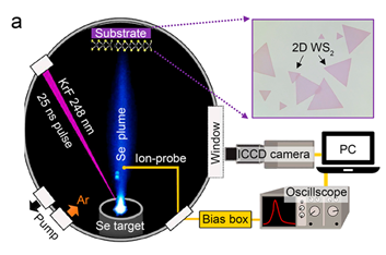 Figure 1: Schematic of pulsed laser deposition. It uses a krypton fluoride (KrF) laser pulse that is 25 nanoseconds (ns) long onto a bed of selenium (Se), which sublimes into the argon atmosphere, rising until it deposits on the substrate while interacting the other materials (either tungsten, W, or molybdenum, Mo). Unfortunately, this process (PLD) has a problem, which is that it is impossible to tell how much the material has grown without a diagnostic tool until you stop depositing, undo the vacuum chamber, and put the substrate under an optical microscope. This is time consuming, especially because you might have to immediately put it back, re-engage the vacuum chamber, heat it up, and begin growth again if there is not enough material. You may even have to do this multiple times. Because of this, many places will put a diagnostic tool called RHEED, or reflection high-energy electron diffraction, to monitor the growth. RHEED is quite costly, though, and it still involves a little bit of guesswork for ensuring proper growth. Therefore, we wanted to develop a new technique that would incorporate cheaper equipment, or equipment that most labs would already own. For labs that already have equipment like pulsed laser deposition, continuous wave red-light lasers are fairly easy to obtain (if they don’t already have them already). What if we could use a cheap laser to monitor the growth instead of a very expensive RHEED tool? We could use a similar setup as RHEED, where a beam (of light instead of electrons) reflects off the surface where the growth occurs into a photodiode that measures the change in reflectivity of the sample (see figure below), which decreases as growth increases. One of the concerns, however, is that the difference in reflectivity with such a simple setup would not even be detectable. 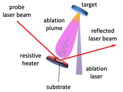 Figure 2: Laser diagnostic setup for a pulsed laser deposition system. The diagnostic laser is the "probe" laser beam My first invitation to the project was the group leader (my boss’s boss) walked by my desk and told me to come see their first experiment in testing whether the reflectivity could be used to monitor growth. They setup the first experiment using an oscilloscope to actively monitor the reflectivity change. It was difficult to read (and did not record any data, which we knew but were hoping to at least offer proof of concept), but it at least seemed promising but was not entirely clear. We needed to tweak the setup a bit, add a reference diode, and align the optics a bit better. Since I was experienced with coding in LabVIEW, they asked me to be responsible for all of the monitoring code to receive information off the photodiode so it could be actively monitored and data recorded during growth. Therefore, I spent a good amount of the next two days putting together a program that could work with the equipment in the lab in LabVIEW and display and track the relevant information. I got a program together in time for a test on the evening of Thursday, October 11, 2018. After a few trial setups and tests, we started our first official experiment at around 7:20pm. A group of 6 of us (two post-docs, a staff scientist, a visiting scientist from Denmark, a group leader, and me, a lowly undergrad) were all watching with anticipation the program I had made display reflectivity data as we started deposition. As the PLD synthesis began, we did not see any changes at first, but then our hopes were realized as reflectivity started rapidly dropping. We all exclaimed with excitement. As the synthesis continued and eventually stopped, reflectivity stabilized at a minimum value and continued oscillation. The data looked similar to that plotted below. 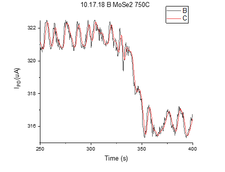 Figure 3: Plot of photodiode current vs time during synthesis (which follows the decrease in reflectivity of the surface) Elated by the success, we all decided to go out to dinner to celebrate. It was a great experience to be able to have such a clear research victory in partnership with people well-above my paygrade. I loved being part of a team that was invested in the project, and getting to hang out with a group leader in the lab til 8pm and then, following a successful synthesis, going to dinner afterward, was a great memory I will not forget. As it turns out, we could optimize the approach well beyond our first attempt. The first attempt used a fairly conventional substate, which was silicon with an SiO2 layer with 300 nanometer (nm) thickness on top. However, what happens if we use a different substrate, such as one where the SiO2 layer is only 90 nm? Somewhat randomly, we tried that a couple weeks later. As it turns out, this changes the results even more substantially in our favor! The thinner coating makes the reflectivity difference during growth much bigger. The first several syntheses only saw around 1.5% change in reflectivity, but the new substrates showed 20-25% reflectivity change! This can be seen in the plot below. Another big difference is that now you can actually see each individual step from each laser pulse (subsequent experiments showed this even more clearly). That enables much higher resolution study, and even transient analysis to study the kinetics.  Figure 4: Larger reflectivity change due to 90 nm SiO2 substrate The next step in the project was to optimize this method, which they asked me to do in MATLAB starting with a model they had built in a previous project. I adapted the model to the current project, and then started calculations to find what substrates would be optimum for how many layers of material growth in which the researcher was interested. As it turns out, the substrate coating can have a huge impact on the reflectivity behavior following growth. For example, an Al2O3 coating can show an increase in reflectivity of an order of magnitude at one thickness or a decrease in reflectivity of a factor of 2 depending on the thickness. Furthermore, absolute reflectivity is another consideration, because if the absolute signal is so low so as to be undetectable, then it does not matter what the normalized or relative reflectivity is. It was determined that an 85 nm of SiO2 is an optimum value for growing monolayer materials, as the contrast is at a minimum, while if the target is pentalayered materials, then 125 nm SiO2 coating is ideal. 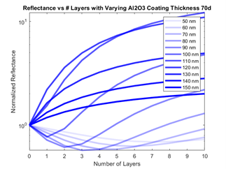 Figure 5: Calculated normalized reflectance of a Al2O3 coated Si substrate All in all, I am very glad I got to be part of this project and discovery which was published two years later in 2D Materials with the title, “In situ laser reflectivity to monitor and control the nucleation and growth of atomically thin 2D materials” (Accepted Manuscript PDF). I am glad my code both in LabVIEW and MATLAB played an important role in the development and completion of this project. Finally, I hope this method can help labs without access to RHEED to be able to more easily monitor their growths to make experimental results become even simpler and faster, as this method can save researchers hundreds of hours.
0 Comments
|
ArchivesCategories |
 RSS Feed
